
1 year by cncdivi
I’ve wanted a small engine project for some time, having seen some Stuart Turner models up close and personal, as well as having looked at a number of pictures on various web sites. The question was which engine would be suitably interesting and pleasing when finished, but at the same time not too terribly hard to build? After keeping the project back of mind for some time and just keeping an eye out, I came across Elmer Verburg’s Reversing Twin Wobbler, and feel it is a suitable possibility. Elmer Verburg was an HSM of surpassing skill and unique engine designs that may be built from scratch. They’re all quite unique and very pleasing. He wrote a book at one time that collected the designs and was a frequent contributor to ModelTec magazine. At this point, Elmer has passed away, but his legacy of elegant and lovely models has lived on, and many HSM’s have constructed his designs. If you can find a copy of his book, by all accounts you should buy it, whatever the cost. If not, cruise the web. There are a variety of sources, including a Yahoo Group that has reproduced all of the Verburg plans online.
I suspect this little engine would make a great CNC project if you have a CNC mill. I will have someday, but I’ll be making my first edition of this engine manually.
| Picture of Other Verburg Wobblers |
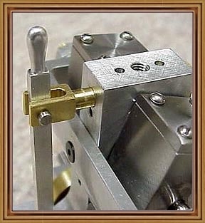
Of the Verburg engine designs available, the Reversible Vertical Twin Wobbler seems to have been very popular, as it is easily found on the net. Here are some typical photos:


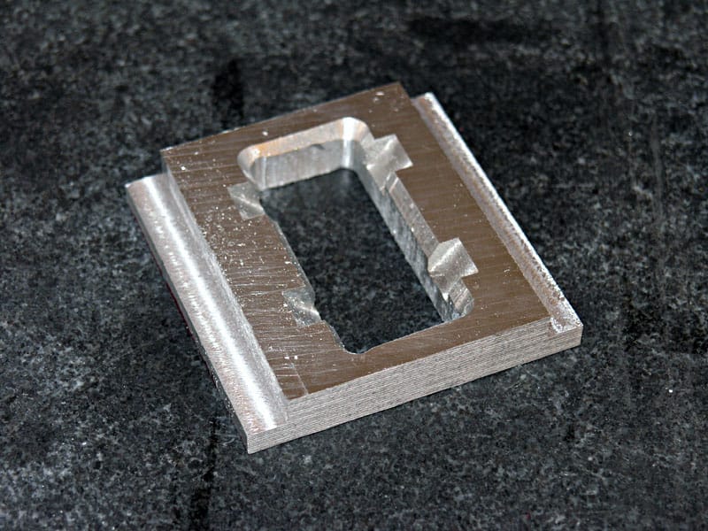
| Base |
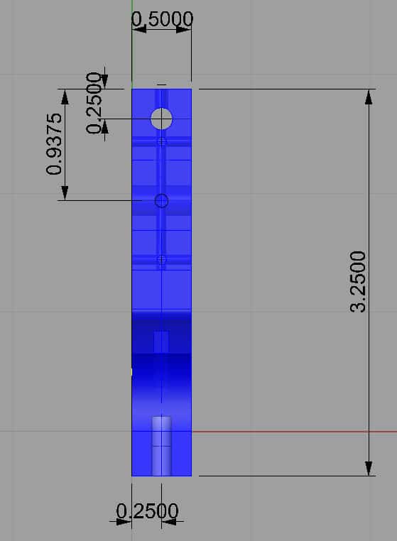
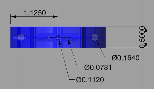
Let’s start out building the base. Here is my Rhino drawing with dimensions:
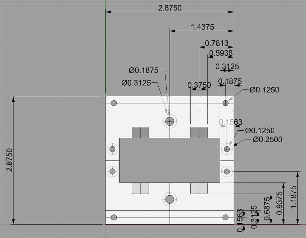
Top View of the Base

Perspective View of the Base. Note: Crank clearance slots are 45 degree angles.
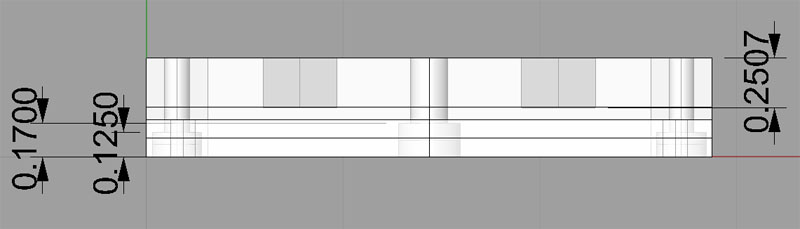
Front View
The base looks pretty straightforward. Need to start with some 1/2″ stock, I’m using 6061 aluminum. I plan to do the center hole first, followed by the crank clearance cutouts, the I’ll mill out the mounting rails, and lastly will drill the holes. All right then, let’s get started!
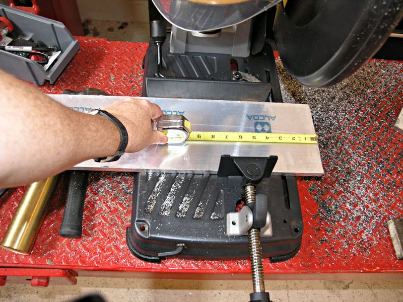
First task is to slice off some stock with my De Walt Multicutter. Need approx 3″. I’ll mill the other dimension. This is 1/2″ thick 6061 MIC-6 aluminum, which means its ground very flat on 2 sides. Nice stuff!
Next I am fly cutting the 2 long edges so the block will be square for layout. The ends will get cut too, but with an endmill…
Once the long edges were square, I used a rougher to cut the edge down until I had the right 2.875″ height…
See, I promised I’d square the edge with an endmill. Since I am cutting this plate in half, I won’t bother squaring the other edge…
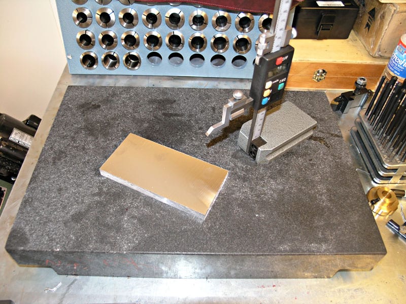
Next Stop: Surface Plate, Height Gage, and Layout. Gotta Put Dychem Machinist’s Dye on First Though…
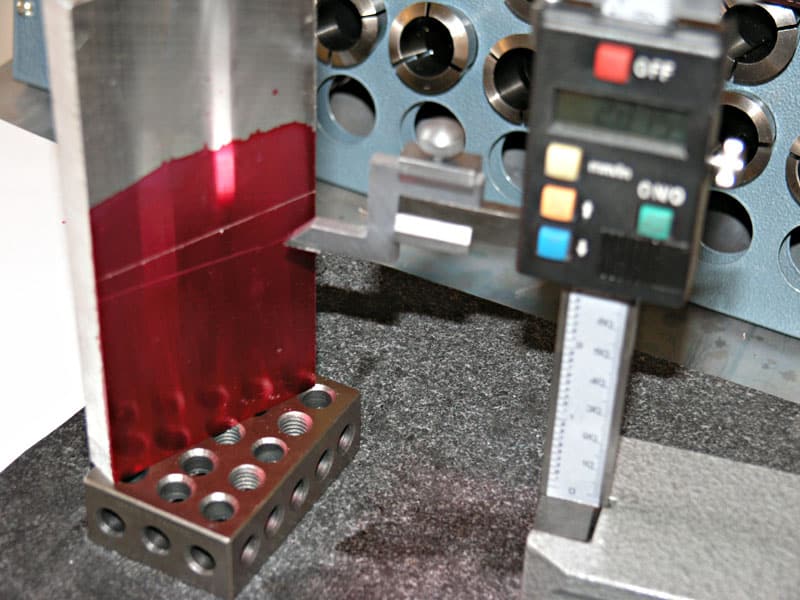
Sorry for the Blur! Why is it on a 1-2-3 block? Because the height gage doesn’t measure down to zero. So, I zero it on the 1-2-3 block, then take my measurements from there. The red Dynchem helps make it easy to see scribe lines. Here I am scribing a line at 2.875″, which will be the edge of the base plate.
I’m just going to use the mill to cut this thing to length and square the other edge at the same time…
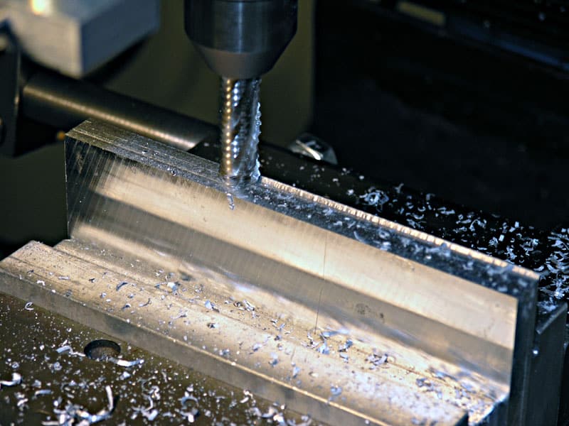
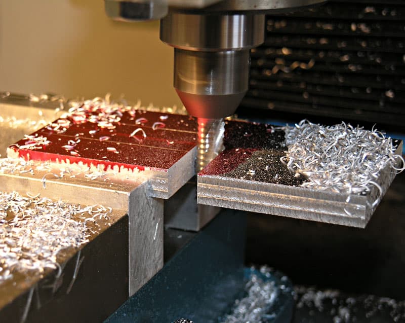
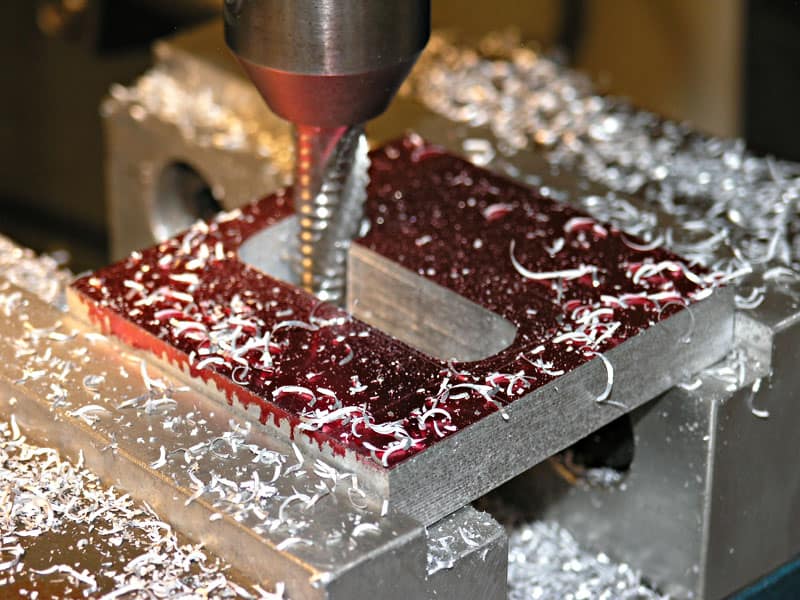
Next, I cut an initial slot in the middle. I ramped down to get there, working things back and forth on the X-Axis while steadily increasing depth of cut until I had made it all the way through the block…
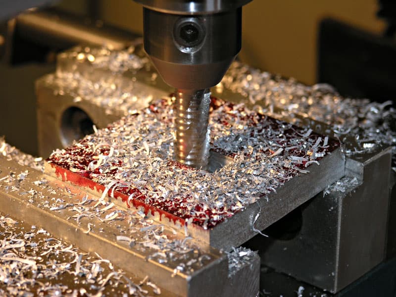
Cutter gets buried in chips! This is where some flood coolant or at least an air nozzle would be nice to keep the chips evacuated…
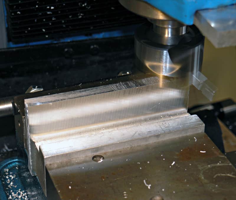
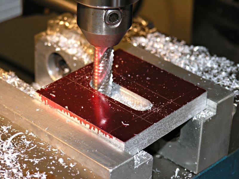
After I got to full depth, I started widening the racetrack until I had cut all the way out to the layout lines. It’s hard to get the corners just right!
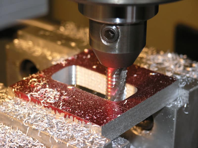
We’re nearly as far as my 1/2″ end mill can go…

For the last part so I could get as far into the corners as possible, I switched to a 5mm diameter endmill I had. It was the smallest thing laying around…
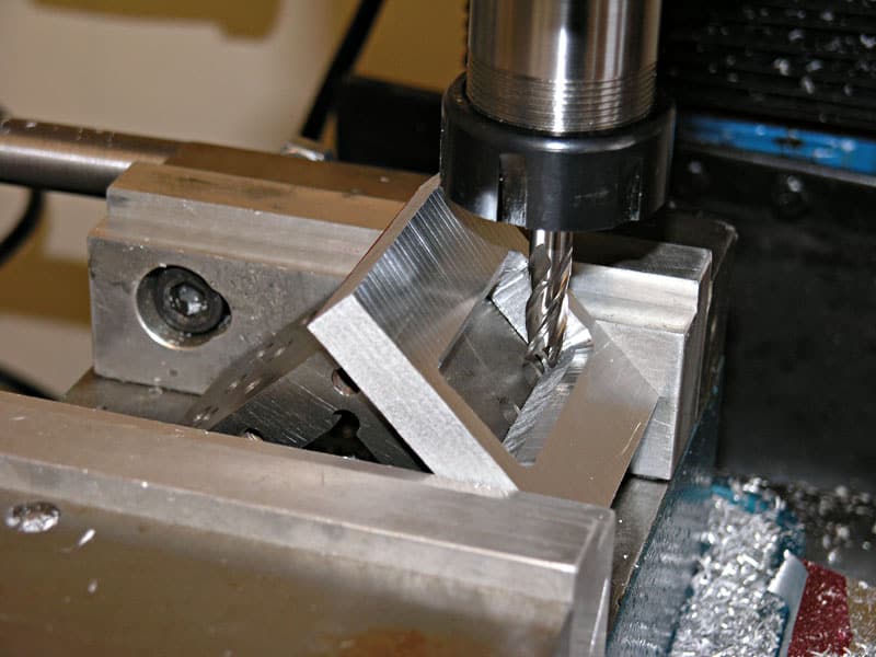
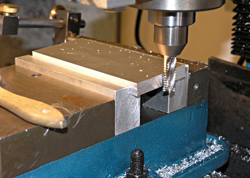
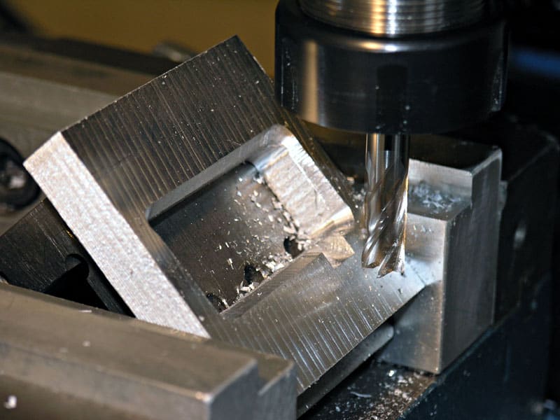
Getting ready to cut the 45 degree crank clearance pockets. Note I chamfered the edge of the hole…
Yes Virginia, that’s an angle plate sitting on its face to provide the 45 degree reference…
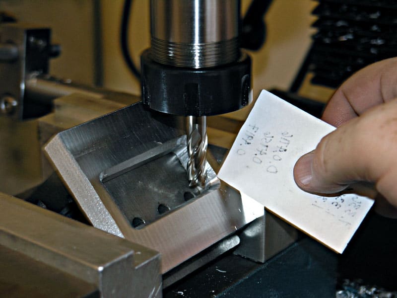
To measure, I touched off the right edge, then backed off with my handwheel graduations the appropriate amount shown on the drawings…
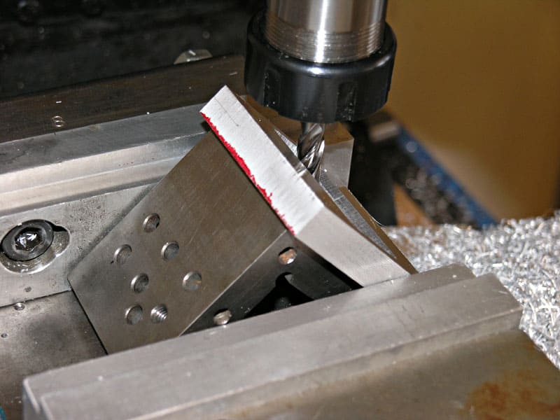
Zip, zip, zip, and we’re done with this one…
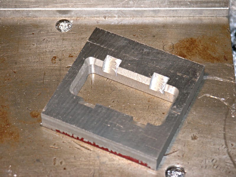
Got dem pockets done now!
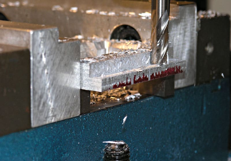
Now we cut the mounting flange. I was trying to climb mill where possible on these…
Milling is done. Time for drilling next…
| Crank Bearings |
The crank bearings are made of brass, but are fairly simple in design:
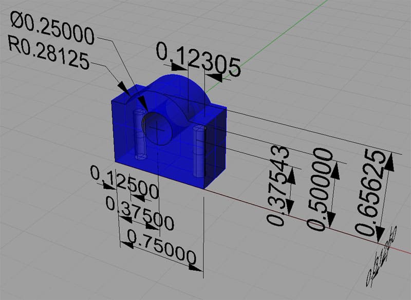
Perspective View…
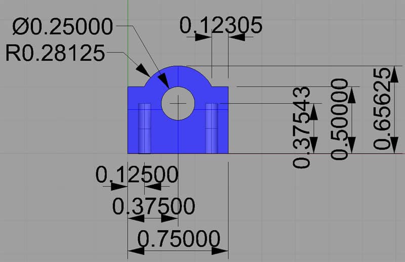
Front View. The mounting holes are 4-40…

Right View…
Okay, we need 2 of these little guys made from brass. A piece of brass plate in the neighborhood of 3/4″ square by 5/16″ or 1/2″ thick should do nicely as a starting point. Alternatively, some 1″ diameter round stock may also be used if you don’t have any brass plate on hand (I didn’t).
| Column |
The column is the most complicated piece to machine because it has a number of features, holes, and curves:
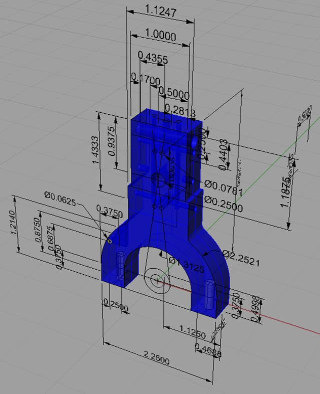
Perspective View…

Front view…
Right view…
Top view…
Like what you read on CNCCookbook?
Join 100,000+ CNC'ers! Get our latest blog posts delivered straight to your email inbox once a week for free. Plus, we’ll give you access to some great CNC reference materials including:
- Our Big List of over 200 CNC Tips and Techniques
- Our Free GCode Programming Basics Course
- And more!
Just enter your name and email address below:
100% Privacy: We will never Spam you!
Recently updated on February 28th, 2023 at 04:26 pm

Bob is responsible for the development and implementation of the popular G-Wizard CNC Software. Bob is also the founder of CNCCookbook, the largest CNC-related blog on the Internet.


